Skema Mixer 6 Ch 505p3a
This document was ed by and they confirmed that they have the permission to share it. If you are author or own the copyright of this book, please report to us by using this report form. Report 445h4w
Overview 1s532p
& View Skema Mixer 6 Ch as PDF for free.
More details 6h715l
- Words: 7,457
- Pages: 39
SKEMA MIXER 6 CH
Audio MIXER Modular dengan 6 dan saluran input
banyak teman-teman bertanya sirkuit AUDIO MIXER, untuk berbagai menggunakan. Saya akan mulai dengan rangkaian yang dapat Anda memproduksi, seperti yang And Anda dapat menempatkan dalam modul input sirkuit apapun Anda inginkan, tergantung pada penggunaan yan berniat MIXER, sama juga untuk jumlah saluran masukan, bahwa Anda akan pembuatan. Di bawah ini saya akan memberikan cukup sirkuit dengan berbagai tingkat kualitas dan kompleksitas. Semua sirkuit yang mengusulkan dan sederhana juga mereka mempertahankan, tingkat yang sangat baik kualitas. Bagi mereka yang mereka tertarik, mereka dapat membuat beberapa kesabaran. Se akan memberikan proyek, profesional tingkat konsol dari campuran sinyal suara.
Dalam gambar 1 ada sirkuit utama MIXER-6Ch. Itu dikuasai oleh 6 saluran masukan. Saluran dari CH 1terpisah untuk setiap sirkuit. Output dari masing-masing saluran drive RV1-6, potesometer peraturan tin merupakan output dari MIXER, mereka yang telah memperoleh satu dan mereka membuat isolasi pentin mungkin perlu. .Koleksi R1.....12=4.7Kohms R13.....24=10Kohms R25-26=22Kohms R27-30-34-39=100ohms R28-29-36-37=100Kohms R31-42=10Kohms R32-41=4.7Kohms R33-40=10Kohms R35-38=47ohms All the Resistors is 1/4W 1% metal film
Pilihan sederhana muncul dalam Fig. 2, asimetris [ketidakseimbangan] sehubungan masukan. Menggun beton. Pilihan saya sendiri: IC1 NE5534 - NE5532 - LM833-TL072-TL074.
Dalam Fig. 3, muncul satu tahap dengan banyak karakteristik yang lebih baik, dalam hubungan simetris
Dalam gambar 4-5, ada dua pilihan untuk preamplifiers mikrofon yang menggunakan transistor, di asim
Untuk modul input stereo, ada dua pilihan, yang muncul pada gambar 6-7. Pilihan pertama dalam gamb
8 GB, ada preamplifier klasik agar koreksi RIAA, bagi mereka yang mereka memaksa mereka mengguna
Dalam gambar 9, ada sirkuit yang simpel dan klasik EQUALIZER, tiga band, rendah, mid dan high frekue
Catu daya dalam gambar 10, dia sangat sederhana dalam mendesain nya. Ada empat regulator yang kita meny benaman. Baik transformator T1, ditempatkan jauh dengan sirkuit sisanya.
Dalam rajah 11, muncul berbagai pilihan sambungan untuk berbagai jenis busi, yang dapat Anda gunak
MIXER-6Ch, dapat diproduksi dalam kotak, yang di atas permukaan akan memiliki kecenderungan terte * Jika Anda menggunakan NE5534, seharusnya Anda menempatkan kapasitor 22pF antara pin 5 dan 8.
Banyak teman-teman bertanya apakah itu mungkin dalam MIXER s ada juga sirkuit monitor, sehingga mungk yang mengatur tingkat untuk headphone penguat. Sinyal ini dikenai dengan terutama sinyal, tetapi hanya di p
rangkaian mixer audio Rabu, 25 September 2013
Rangkaian Mixer 3 Chanel
Rangkaian mixer 3 chanel pada gambar dibawah dibuat menggunakan penguat tegangan dari transistor yang disusun beberapa tingkat. Mixer 3 chanel ini terdiri dari 3 buah pre-amp mic transistor dan penguat tegangan dengan transistor darlington. Untuk mengoperasikan rangkaian mixer 3 chanel ini diperlukan sumber tegangan DC + 9 volt yang dapat diambil dari suatu batere maupun dari power supply. Berikut adalah gambar rangkaian dan komponen untuk membuat rangkaian mixer audio 3 chanel dimaksud. Rangkaian Mixer 3 Chanel Transistor Rangkaian Mixer 3 Chanel Transistor,Rangkaian mixer 3 chanel,Mixer 3 chanel,mixer audio,mixer sound sistem,harga mixer audio,harga mixer sound sitem,jual mixer soud sistem,jual mixer audio murah,rangkaian mixer audio,skema mixer audio,pcb mixer audio,mixer audio rakitan,merakit ,membuat mixer audio,cara buat mixer audio,cara seting mixer audio,menggunakan ,cara buat mixer audio,cara seting mixer audio,menggunakan mixer audio,mengoperasikan mixer sound sistem,mixer yamaha,mixer behringer,mixer pro,mixer transistor,mixer sederhan,rangkaian mixer sederhana,skema mixer audio sederhana.
Daftar Komponen Rangkaian Mixer 3 Chanel Transistor P1 = 5K P2 = 5K P3 = 5K R1 = 180K R2 = 2M2 R3 = 750R R4 = 1K R5 = 15K
R6 = 220R R7 = 1.5K R8 = 820R R9 = 150R R10 = 100K R11 = 180K R12 = 2.2M R13 = 750R R14 = 1K R15 = 180K R16 = 2M2 R17 = 750R R18 = 1K C1 = 1µF-63V C2 = 100µF-25V C3 = 220µF-25V C4 = 100µF-25V C5 = 220µF-25V C6 = 1µF-63V C7 = 100µF-25V C8 = 1µF-63V C9 = 100µF-25V Q1 = BC550C Q2 = BC547 Q3 = BC557 Q4 = BC550C Q5 = BC550C B1 = 9V
J1,J2,J3 = 3mm Mono Jack SW1,2,3,4 = SPST Toggle Pada rangkaian mixer 3 chanel transistor diatas pada dasarnya terdiri dari 2 bagian utama sebagai berikut. Pre-Amplifier Microphone. Bagian pre-amp mic berfungsi sebgai penguat tegangan dari output microphone sebelum dicampur dengan sinyal yang lain. Rangkaian pre-amp mic ini dibangun menggunakan penguat tegangan dari transistor NPN tipe BC550C. Pre-amp mic ini di desain untuk menguatkan sinyal output dari microphone tipe dinamic. Pada tiap preamp mic rangkaian mixer 3 chanel diatas dilengkapi pengatur penguatan sinyal dari microphone mengunakan potensiometer dan pembatas penguatan level sinyal menggunakan sebuah saklar untuk tiap chanelnya. Penguat Tegangan Transistor Rangkaian penguat tegangan dengan transistor darlington ini berfungsi untuk menguatkan sinyal dari pre-amp mic dan sebagai bagian pencampur sinyal-sinyal dari pre-amp mic yang diberikan ke rangkaian penguat tegangan ini. Rangkaian penguat tegangan ini dibangun menggunakan transistor NPN tipe BC547 dan BC557 yang dirangkai secara darlington. Pada bagian ini sinyal dari pre-amp mic dicampur secara langsung dan diberikan sebagai input rangkaian mixer. Di bawah ini kami tampilkan Rangkaian Audio Mixer yang cukup handal. Silakan Anda lihat dan pelajari. Siapa tahu Anda tertarik untuk membuatnya.
Gambar Skema Rangkaian Audio Mixer Mixer adalah salah satu perangkat paling populer setelah microphone. Kita lebih mengenalnya dengan sebutan mixer, mungkin kebanyakan kita menyebutnya demikian karena fungsinya yang memang mencampur segala suara yang masuk, kemudian men-seimbangkannya, menjadikannya dua (L-R kalau stereo, dan satu kalau mono), kemudian mengirimkannya ke cross-over baru ke power amplifier dan akhirnya ke speaker. Audio Musik1.Mixer 8 chanel Stereo Sound System 2.Microphon
3.Speaker Aktif 4.Probe kabel secukupnya C.DASAR TEORI Mixing adalah salah satu perangkat paling populer setelah microphone. Kita lebih mengenalnya dengan sebutan mixer, mungkin kebanyakan kita menyebutnya demikian karena fungsinya yang memang mencampur segala suara yang masuk, kemudian men-seimbangkannya, menjadikannya dua (L-R kalau stereo, dan satu kalau mono), kemudian mengirimkannya ke cross-over baru ke power amplifier dan akhirnya ke speaker. Konsul mixing (Audio Mixer) adalah pusat dari sistem tata suara dimana operator dapat menyampur, menyamakan dan menambah efek-efek pada sumber-sumber suara. Berbagai konsul mixer dapat dipakai untuk berbagai keperluan dalam satu sistem tata suara tunggal. Dalam tata suara, konsul mixer utama (FOH, Front of House) harus berada dimana operator dapat melihat dan mendengar aksi di panggung. Mixing dengan booth monitor terdekat akan mencegah operator dari pendengaran yang campur aduk antara suara artis, umpan balik Loudspeaker utama, gaduh penonton dan juga efek akustik ruangan. Pada pertunjukan skala besar, sering kali menggunakan konsul mixing untuk monitor panggung secara terpisah, dimana diperuntukkan untuk menciptakan monitor hasil mix bagi monitor-monitor diatas panggung. Konsul-konsul ini sering kali terletak di samping panggung sehingga operator dapat berkomunikasi dengan yang sedang tampil diatas panggung. Sehingga akan memudahkan saat ada gamgguangangguan kecil karena cacat intrumen atau karena faktor lain yg menyebabkan suara cacat Gambar dasar suatu Mixer dengan 3 input MIC. D.LANGKAH KERJA 1.Siapkan Alat dan Bahan yang di butuhkan 2.Rangkailah Mixer dengan Microphon dan Speaker Aktif 3.Gambarlah Mixer Stereo Sound System lengkap dengan tombol-tombolnya 4.Jelaskan Fungsi dari masing-masing tombol Mixer 5.Untuk mengetahui fungi dari masing-masing tombol terlebih dahulu aturaturlah tombol Mixer sehingga suara bisa keluar 6.Setelah langkah nomor 1 sampai dengan 5 dilakukan, kemudian tuliskan data yang sesuai didapat dari hasil praktikum tersebut yg mengunakan MIXER. ANALISA DATA Mixer adalah salah satu perangkat paling populer setelah microphone. Kita lebih mengenalnya dengan sebutan mixer, mungkin kebanyakan kita menyebutnya demikian karena fungsinya yang memang mencampur segala suara yang masuk, kemudian men-seimbangkannya, menjadikannya dua (L-R kalau stereo, dan satu kalau mono), kemudian mengirimkannya ke cross-over baru ke power amplifier dan akhirnya ke speaker. Bagian – bagian pengatur pada mixer 8 chanel dan fungsinya : 1. Mic/line Switch tekan ini untuk merubah sirkit gain control. Tergantung apakah yang
menjadi input adalah mic, effect return atau tape deck/CD. Pada banyak mixing console terdapat terminal input yang terpisah antara mic dan line input pada channel yang sama. Input mic biasanya menggunakan tipe konektor balans 3 pin XLR atau kadang biasa disebut jack Canon. Sedangkan line input menggunakan jack seperti yang biasa dipakai jack gitar. Hal ini memungkinkan untuk mencolokkan dua input yang berbeda dalam satu channel, dan switch ini untuk mengaktifkan salah satu input yang kita inginkan diantara keduanya. Sebagai contoh, anda dapat mencolokkan effect return dngan gain yang diset rendah pada mic input kemudian mencolokkan lagi tape deck pada line input channel yang sama. Pada saat band sedang show dan tape deck tidak dibutuhkan, anda tinggal men-switch tombol tersebut pada posisi mic. Kemudian pada saat band telah selesai dan butuh playback musik dari tape deck/CD, anda juga tinggal men-switchnya pada posisi line. Ini bisa dilakukan untuk menghemat channel, khususnya apabila console yang digunakan tidak terlalu besar. 2. Gain Disebut juga input level atau trim, biasa terdapat pada urutan paling atas dari setiap channel mixing console. Fungsinya adalah untuk menentukan seberapa sensitive input yang kita inginkan diterima oleh console. Apakah berupa signal mic atau berupa signal line (keyboard, tape deck, dll). Tombol ini akan sangat membantu untuk mengatur signal yang akan masuk ke console. Bila signal lemah, maka dapat dilakukan penambahan, bila terlalu kuat dapat dikurangi. Contoh : untuk penyanyi yang suaranya lemah atau tidak meiliki power yang baik, diperlukan penambahan gain yang lebih. Sedangkan untuk gebukan kick drum, mungkin dilakukan dengan sedikit penambahan. Ini dilakukan agar menjaga setiap input yang masuk ke mixer tetap optimal. Input gain yang terlalu besar akan menyebabkan distorsi, sedangkan kalau terlalu lemah akan membutuhkan penambahan yang bila berlebihan akan menyebabkan noise. Jadi input gain stage adalah hal yang paling penting dan kritis, karena dari sinilah semua suara yang berkualitas dimulai. Makanya usahakanlah untuk menjaga agar setiap input tetap clean dan clear sebisa mungkin. Sebab noise dan distorsi yang diakibatkan dalam poin ini akan mengalir terus ke seluruh system dan membuat seluruhnya jadi terganggu. Bila ternyata input gain sangat besar atau bahkan terlalu besar sehigga setelah dikurangi juga masih saja terlalu kuat, maka untuk itu terdapat switch PAD pada console yang fungsinya adalah untuk menurunkan gain input signal mulai –20 sampai –30 db. 3. EQ pada channel Pada setiap channel di mixing console selalu terdapat Equalizer Section.yang terdiri dari BASS, MIDLE, TREBLE Fungsinya yaitu sebagai pengatur tone untuk me-modifikasi suara yang masuk pada channel tersebut. Umumnya sound engineer melakukan perubahan sound melalui EQ bertujuan dua : 1. Untuk merubah sound instrument menjadi sound yang lebih disukai 2. Mencari karakterisrik suara yg sesuai. 3. untuk mengatasi frekuensi dari input yang bermasalah, misalnya , dengung, overtune, dll.
Pengaturan yang sangat mendasar dari EQ adalah berupa Low, midle dan Hi, kemudian penambahan dan pengurangan (boost/cut). Atau ada juga yang lebih kompleks dengan 4 jalur dengan fungsi yang full parametric. Yang dimaksud fix diatas adalah pada EQ tersebut tidak memiliki tombol untuk mmilih frekuensi yang akan disetting. Karena frekuensi yang akan “dikerjai” telah ditetapkan dari pabrik. Pembagian frekuensi pada EQ jenis ini mirip denga pembagian yang terdapat pada crossover, hanya terdiri atas : 1. Low, dan hi-pada EQ 2way Low 2. Mid dan Hi-pada EQ 3wayLow 3. Low Mid, Hi mid dan Hi-pada EQ 4 way Memutar tombol boost/cut akan memberi pengaruh sampai 12 atau 15 db tergantung mixing console apa yang anda gunakan. Keuntungan EQ yang fix adalah : harga yang relatif ekonomis, terhindar dari kesalahan pmilihanfrekuensi yang akan disetting. Kesalahan seperti ini bisa disebabkan oleh kurang berpengalamnnay sound engineer (penata suara), dan keuntungan yang terakhir adalah hemat waktu dalam pen-settingan. Namun ada juga kekurangannya seperti : kita tidak dapat memilih frekuensi khusus yang kitainginkan. Karena semua frekuensi telah ditetapkan dari pabriknya. 4. EFFEX Effex dalam mixer ini mempunyai suatu fungsi mengirimkan sinyal suara ke rangakain suara EFFEX yaitu biasanya REVERB,ECHO, yang bisa membuat suara si vokal atau instrumen tersebut menjadi lebih baik dengan settinggan yg berbeda-beda sesuai dengan keinginan dan situasi ruangan. Dalam mixer ini dah terdapat effex yaitu ECHO DELAY yang bisa di atur kecapatan effex delaynya sesuai dengan selera yang kita kehendaki. 5. AUX Send Dari tombol putar ini dapat dikirim signal dari channel tersebut keluar mixing console (melalui terminal aux out pada terminal keluaran di belakang mixer), kemudian dari tombol ini juga dapat dikontrol level signal yang dikirimnya tadi. Signal yang dikirim ini terpisah sama sekali dari keluaran master. Ini berguna untuk mengirim signal ke system monitor, atau juga ke berbagai macam unit effec, dan dari keluaran effect dikirim lagi ke channel yang berbeda pada mixing console. Mixer yang pling sederhana sekalipun sedikitnya memiliki satu atau dua AUX SEND. Satu untuk mengirim signal ke monitor dan satu untuk mengrim effect (echo, reverb). 6. PAN (balance) Merupakan potensio Balance yang mengatur keluaran antara R(right) dan L(left) kanan dan kiri untuk keseimbangan masing-masing chanel yang di pakai. 7. Volume Chanel Volume ini adalah volume per chanel yang di pakai untuk mengeluakan ke volume master out, sehingga dari suara per chanel akan bisa di atur sesuai dengan apa yang masuk ke per chanel entah vokal dan instrumen sehingga akan
menghasilkan suara yang bisa sama antara chanel satu denga yang lainnya. 9. Master auxiliary Setiap auxiliary dari channel memiliki satu tombol lagi sebagai pengatur level untuk keseluruhannya. Misalnya aux 1 setiap channel memiliki master aux 1 untuk mengatur seluruh level dari aux 1 setiap channel. Begitu juga auxiliary lainnya. Yang berarti bila mixer meiliki 4 auxiliary out, maka akan terdapat 4 auxiliary master. Perhatikan beberapa tombol sejenis seperti Aux Master, Effect Master, Monitor Master, atau sesuatu yang kurang lebih adalah berfungsi sama. Untuk pen-settingan awal putar tombol tersebut pada posisi jam 2, baru lakukan pen-settingan pada channel. Bila ternyata masih kurang kuat, tambah lagi, atau bila terlalu keras, kurangi. Semuanya tergantung situasi. 10. Auxiliary Return Signal yang telah dikirim melalui auxiliary out ke unit effect apakah Delay, Reverb atau lainnya akan dikirim kembali ke mixing console untuk digabungkan dan diseimbangkan secara tepat dengan level dari signal orisinil source tadi. Walupun cukup banyak juga mixing console yang memiliki pengaturan effect return secara khusus. Yang biasanya bukan dalam bentuk slider (potensio geser). Bila memang masih terdapat channel yang dapat digunakan sebagai masukan effect, kita dapat melakukan pegaturan sengan slider yang lebih memudahkan seperti melakukan pengaturan pada channel standard. Namun pengaturan dengan aux return juga sama seperti yang kita lakukan pada channel, hanya dengan memutar ke arah kanan dan kiri untuk menambah dan mengurangi level effect. Perhatikan! Bila anda membuka sedikit saja Aux Send dari channel yang telah digunakan sebagai effect return, akan berakibat feed back dan noise. Atasi segera dengan menurunkan level dari channel, kemudian periksa Aux Send pada channel. 11. Master Volume (Right-Left) Volume ini adalah volume out yaitu pusat dari keseluruhan dari chanel 1-8 chanel yang berfungsi mengatur output keluaran antara output R(Right) dan L(Left), yang menuju ke masing- masing power amplifier yang di pakai, sehingga akan bisa sekali di dapatkan pusat pengaturan volume keseluruhan chanel dari master volume.
3 Channel Audio Mixer Circuit Posted by Received by Email in Audio with 27 comments Tagged with: audio mixers•LM3900
Enabling the IoT with the Intel Edison development platform The Intel Edison development platform is designed to lower the barriers to entry for Product Designers to rapidly prototype and produce "Internet of Things" (IoT)
and wearables computing products. This on-demand webinar provides an opportunity to learn about Edison, development tools and IoT applications read more...
This audio mixer circuit uses an LM3900 IC but is not a profesional audio dj mixer. The IC houses four integrated Norton amplifiers. The advantage of using the four op amps is that they only need a single power supply. Since this amplifier circuit is current controlled, the DC bias is dependent on the coupling.
The schematic diagram shows inverting AC-Norton amplifiers. The DC output must be set at 50 percent of the power supply. In this case, a maximum output can be achieved without distortion (also called symmetrical limitation through overdrive). In deg this mini audio mixer circuit diagram you can freely choose the value of the resistor R2 (100k in the mixer schematic). Set the AC voltage amplification factor through the ration of R2/R1. To set the amplifier gain correctly, choose the value of R4=2R2 (double the value of R2).
Diagram 1.0 shows the 3-channel sound mixer circuit using three Norton-opamps. The input levels can be set by potentiometers P1 or P3. Furthermore, each input level can be trimmed with the help of trimmers pots P4 to P6 to adapt each input to the source. The resistors at the non-inverting inputs of the opamps work as DC bias and set the DC output at 50 percent of the power supply for this powered audio mixer. All three input signals are summed by the fourth opamp A4 through the resistors R3, R7 and R11. The commom volume level is cotrolled through the potentiometer P7. You can switch an input channel on or off through the switches S1 and S3. An input channel is turned off when its switch is closed. It is also possible to replace these mechanical switches with transistor gates. By doing so, you can build an analog multiplexer circuit that can be easily expanded by several inputs. For more audio mixers check the list bellow. 3 channel audio mixer PCB and Parts layout
Audio Mixer external wiring layout
Audio Mixer circuit diagram
Single Transistor Audio Mixer Circuit Posted by Received by Email in Audio with no comments yet Tagged with: audio mixers
Enabling the IoT with the Intel Edison development platform The Intel Edison development platform is designed to lower the barriers to entry for Product Designers to rapidly prototype and produce "Internet of Things" (IoT) and wearables computing products. This on-demand webinar provides an opportunity to learn about Edison, development tools and IoT applications read more...
This single transistor audio mixer is used in an amplifier circuit design with base driven transistor and with its emitter being current controlled, most of the driving current flows through the collector away. Using the values in the audio mixer circuit shown in the diagram, the collector current will be about 1 mA. At 15 volts power supply, the input resistors should
be 33K. Additional input lines can be connected to the emitter line. Each added input must be series limited by the 33K resistor.
Audio mixer circuit diagram
Mixer PCB Layout
One Transistor Audio Mixer Posted by P. Marian in Audio with 4 comments Tagged with: audio mixers
Enabling the IoT with the Intel Edison development platform The Intel Edison development platform is designed to lower the barriers to entry for Product Designers to rapidly prototype and produce "Internet of Things" (IoT) and wearables computing products. This on-demand webinar provides an opportunity to learn about Edison, development tools and IoT applications read more...
The simplest one transistor audio mixer circuit diagram on the net. It has only one transistor and can as many audio signal as you can afford. BC109C is a very cheap transistor and with a few resistors and capacitors you can build quickly a mixer circuit diagram that you can use in your pirate radio or wherever you want, imagination is the final frontier. Please keep in mind not to use higher voltages than 22V as a power supply for this audio mixer.
Audio mixer circuit diagram
Simple Audio Mixer Circuit Posted by P. Marian in Audio with 2 comments Tagged with: audio mixers
Enabling the IoT with the Intel Edison development platform The Intel Edison development platform is designed to lower the barriers to entry for Product Designers to rapidly prototype and produce "Internet of Things" (IoT) and wearables computing products. This on-demand webinar provides an opportunity to learn about Edison, development tools and IoT applications read more...
The simple audio mixer circuit is built on common base principle, where input voltages are transformed in alternative currents wich are summed to form the alternative current component for the collector. The total amplification is R6/Ri, where Ri is one of the input resistors. I’ve build this mixer for a little fm transmitter and works great.
Audio Mixer Circuit Schematic
simple audio mixer circuit schematic A simple mixer with 3 line inputs and 3 mic inputs using commonly available parts.
Circuit Notes The mixer circuit above has 3 line inputs and 3 mic inputs. The mic inputs are suitable for low impedance 200-1000R dynamic microphones. An ECM or condenser mic can also be used, but must have bias applied via a series resistor. As with any mixer circuit, a slight loss is always introduced. The final summing amplifier has a gain of 2 or 6dB to overcome this. The Input line level should be around 200mV RMS. The Pinouts for LM741, LF351 ,TL071 and NE5534 are shown below. Pinouts for other IC's can be found on the pinout page.
The mic inputs are amplified about 100 times or 40dB, the total gain of the mixer including the summing amplifier is 46dB. The mic input is designed for microphones with outputs of about 2mV RMS at 1 meter. Most dynamic microphones meet this standard. The choice of op-amp is not critical in this circuit. Bipolar, FET input or MOS type op-amps can therefore be used; i.e 741, LF351, TL061, TL071, CA3140 etc. The power supply is a dual positive and negative supply, two 9 Volt batteries may be used as shown above or a power supply is recommended for longer periods of use.
Simple Mixer Schematics PREAMBLE: I've been cooking audio circuits for so long now I no-longer need a recipe. A lot of the theory I have forgotten over the years because I've just gotten to know the circuits by instinct. But this should serve as something of a guide to deg mixers from scratch. The idea: Most people reading this would be well aware of what a mixer is used for but I'll reiterate here. The job of an Audio mixer is to combine various audio signals into a single audio signal. It is better known in electronic as a summing circuit. That is to say that the output is the sum of all of the inputs. A summing note is often represented as a circle with a PLUS (+) symbol in it. Audio is of course an AC (Alternating current) signal but if we look at the incoming signals as a frozen moment in time we can represent it as 2 or more DC voltages. This is only useful to illustrate the point.
If we had two signals to be mixed. The first was 2 volts and the second was 3, the output should be the sum of these two voltages. 2+3=5. If on the other hand the two voltages were 2 volts and -3 volts then the output would be -1 volt. We are now subtracting 3 volts from the +2 volts leaving -3. It is important to recognise that we are dealing with what is known as a bipolar signal. That is one that can be positive or negative around a zero base-line. When you get to the stage of adding many signals together, the complexity grows. In1 + In2 + In3 + In4 + .... and so on. Because each incoming signal has it's own load impedance it is impractical just to wire all of them together and hope for the best. Especially when the following device you are trying to mix into also represents it's own load impedance. Sometimes you may be able to get away with it because the combined impedance is quite high. However most of the time it drags the whole network down and causes one or more devices to fail or distort or what ever. Usually no damage is done but it just won't work. What is required is a little load isolation. (See Circuit 1: ive mixer) The trade off is that you can't use terribly high value resistors because of the losses that they may cause. Especially if the load impedance of the following device is a little low. This will give the effect of severely attenuating some or all of the signals. A practical trade off has to be reached and this is as much trial and error as anything because the conditions change with each new device added or changed. The device used at the summing node, IE: an amplifier or tape deck should be able to provide enough gain to compensate for the combined losses through the resistors and the combined loading of the system. But the loading will change depending on the combination of devices you have hooked into it. This approach also creates another side effect. That is that a signal flowing into the summing node via one source can pollute the audio signals of other devices. Say you had two cassette decks that you wished to mix. However you also wanted to send the audio from cassette deck #1 to an effects processor. The audio from cassette deck #2, although attenuated slightly, will find it's way back to the audio from cassette deck 1 and also go to the effects processor. ACTIVE STAGES: Active Mixer stages that use Op-Amps are generally known as virtual earth pre-amps. These are inverting in nature. 180 degrees out of phase. IE: The signal coming out of the mixer is upside down as compared to that which is entering it. You then need to use another inverting pre-amp to recover the phase. This would seem silly at first until you realize that virtual earth means that the inverting node of the op-amp is held virtually at ground (zero volts) potential. Any signal entering the stage via one resistor cannot find it's way back out of any other resistor. This prevents the audio from *say* one synth, polluting the audio from another. Particularly useful in a Mixer with many busses and sends. Generally speaking the pre-amps stage does not provide any gain. IE: is 1:1 unity gain. A signal ing through a resistor with no load also presents no loss. Even with values beyond 1 meg. Although you may drop the effective current at the other end of the resistor. In this
case the current loss is largely irrelevant. Especially at line-level. And is compensated by the op-amp's drive current in an active system. It is better to have a mixer stage with no gain (or unity gain) because this will not amplify the noise. If good quality op-amps are used, they will not add significantly to the over all noise performance. So the RMS voltage coming out of the mixer should be the same as the sum of all it's inputs. If gain is necessary for a microphone or phono etc, the gain should be a special stage at the top of the chain. IE: the first preamp in the mixer channel. This is then mixed with everything else once the microphone is amplified to line level. This gain stage only adds noise to the microphone and not to the sum of the signals ing through the mixer. It is interesting to note that resistors themselves add noise to a circuit. This is known as thermal noise. Generally speaking the rule of thumb is: The larger the value the resistor, the greater the thermal noise. This may not be significant in mixer stages at line level but where large gains are required it is desirable to use smaller value resistors. (as small as possible within reason.) Of course sometimes this cannot be achieved but is worth ing as a rule of thumb. Metal film resistors have less thermal noise than carbon film resistors and are more temperature stable over all. So now there's two reasons to use Metal films in audio circuits. Virtual Earth: Circuit 2 shows a basic active mixer. It uses 2 virtual earth preamps. One for the summing node and 1 to re-invert the phase of the signal. The summing node (The point at which all the resistors meet) enteres into the inverting input of the op-amp. A resistor is connected between the output of the op-amp and the inverting input. The function off this loop is essentially to limit the open-loop gain of the op-amp. Any signal entering the inverting input of the op-amp will appear at the output but it will be upside down. That is to say 180 degrees out of phase. In other words if you put 2 volts in you'd expect -2 volts out. To achieve unity gain (that is no gain or amplification at all) the resistor must be the same as the summing resistor. In this case 10K. All the summing resistors are 10K and the resistor is 10K. Because the resistor feeds the output signal back to the inverting input of the op-amp @ 180 degrees out of phases it cancels out any gain. It also means that the inverting input of the op-amp is held pretty close (If not exactly) at zero volts. or earth potential. Thus the term "virtual earth". Any signal coming in through the summing resistor is like dumping it to ground via 10K. It theoretically has the same loss. However the resistor of 10K gives the exact opposite in gain. So if you feed 2 volts in you will get 2 volts out only it will be upside down. Because the summing node (The inverting input of the op-amp) is at virtually earth potential, there is little chance that this signal will bleed it's way out to any of the other inputs. Essentially speaking all the audio sources are isolated from each other. However we're still left with the problem of the phase being wrong. If the output of the first op-amp were recombined with one of the other signals at a later stage it would cancel out rather than mix. So we have to re-invert the phase with yet another op-amp. This is a unity gain amplifier just like the first except that there is no summing node as such. (Except for the
resistor of course) The output of these two stages will now be the summ of all the inputs with the correct phase. Because of the inherent compensation of the /opamp/summing node, there is virtually no limit to the number of inputs you can put on this. Most modern op-amps have enough drive capability that 128 inputs would be just peanuts. However it must be ed that you are summing the inputs so if you had a powersupply of say +/- 15 volts, and 4 inputs of +5 volts each, The result would be 20 volts mathematically speaking. But the op-amp can only produce +15 volts so you would be clipping by 25%. Distortion occurs. Most op-amps can't swing exactly to the supply rails so clipping and distortion would be even worse. In practice however most audio signal wouldn't exceed a few hundred milivolts. A 2 volt peak to peak signal is considered to be a very high level. Two more variations: The third circuit shows a Mixer with input attenuation. This is a fairly simple concept. A potentiometer is placed in the signal's path between the source and the summing resistor. When the wiper of the POT is at the top it simply represents a 10K load to the source. 10K is a pretty high value and most line level devices can easily drive this load. With the wiper at the other end of the pot it still represents a 10K load to the source but the input is effectively at ground (Shorted out) so no signal gets through. With the wiper in mid way position the input loading is still 10K, however the signal has to flow through a 5K resistance and is also dumped to ground by 5K. Halving the potential reaching the input resistor/summing node. The fourth and final circuit shows a full on stereo mixer. Two new types of input networks are shown. the first is a stereo-in with balance. Similar to your stereo amplifier etc. A dual gain pot is use for volume whilst balance is single. Note that following the volume pot is a 10K resistor connected to one end of the balance pot. With the wiper in the centre position and connected to ground as it is, means that the incoming audio is virtually running through a 22.5K resistor to ground. That is 10K +(1/2 of 25K) = 22.5K Because of this attenuation the resistor around the virtual earth op-amp is increased to 33K to compensate. This is not exactly unity gain but it comes awfully close. A very slight and probably un-noticeable gain. The other input is MONO in but is pannable between left and right. The same deal as above applies here except that the first two 10K resistors are ed together so that the signal is split across two paths. Strictly speaking the first two 10K resistors in the stereo input are not necessary but are needed for the mono circuit so that the pan pot does not short out the signal when at either extremes of travel. They are included in the stereo input simply to compensate for unity gain over all. This input scheme is the basis for 99% of all large mixing consoles. Driving the busses: Note here that Mixers are more repetitious than complex. The circuits are relatively simple it's just that there's a lot of them. Especially in large recording consoles. Usually these desks are seen in two halves. The input half and the output half. No matter how complex the input half may become, the output half is essentially just a virtual earth pre-amp as described in the circuits above. Often it is required to have many such busses for things like effects sends, subgroups, monitor bus and so on.
One of the beauties of the virtual earth mixer is that there is also virtually no limit to the number of additional busses as well as the main bus. One could arrange an effects send buss that derives it's signal from the same channel as the main bus. Except that each has it's own volume, pan and assignment independent of each other. A FINAL WORD on the CAPACITORS: There are capacitors in two main circuit functions on the schematics above. the first is an electrolytic blocking capacitor. The idea is that a DC voltage can't got through a capacitor in series. What this means is that any DC offset voltage emanating from a preceding stage or source will be knocked on the head. only the AC voltage (The audio signal) will get through. The reason for this is simple. Suppose you had 10 sources each with a +1volt DC offset. This would add up in the mixer stage to be +10 volts. Not exactly desirable. It is therefore usual to use a blocking capacitor to stop this happening. This may not be so in all cases but is a rule of thumb for most audio circuits. The blocking capacitor is placed on the input near to where an unknown source is to enter the circuit. It is also usual to have one on the output stage which blocks any DC from leaving your circuit and propagating into any following equipment. The reason you need them on both input and output is simply that you never know what you might connect your circuit up to and there is no convention. If you are unsure of the polarity required for the blocking capacitor you can use a bi-polar electrolytic. Which is essentially two normal electrolytic capacitors back to back in the one package. The value of these capacitors are not important as long as it has no effect on the audio signal (IE accidently creates a low filter) and the voltage rating is sufficient enough that it won't burn out. Usually 16 volt rating is sufficient. 25 volts to be on the safe side. 50 volts is called "overengineering". The value of the capacitor can be anywhere between 0.1uF to 47uF but usually between 1.0uF and 10uF. The other two capacitors, 27pF and 47pF are optional and for stability of the op-amps. Truth be known these were left in the schematic by accident because I simply modified the circuit from one I was working on at the time of writing. The original circuit was designed to closely approximate another commercial mixer as I was extending it's capabilities. Out of interest these two capacitors cause the op-amps to behave as slight intergrator-filters limiting the top end response slightly above the audio bandwitdth. This is some times necessary where the op-amps used have such a high gain-bandwitch product that they tend to saturate with RF or at least HF signals. Thus becoming unstable in certain situations. Generally speaking these are largely irrelevant to the design. Epilogue: Well hopefully I've provided enough information so you could go out and roll your own designs. And hopefully I've been able to work it in such a way that it's relatively understandable. If there are any mistakes, errors or omissions, please feel free to point them out. But Please no nit-picking. I'm only doing this because of the number of questions asked on this subject and the relative interest for people to design their own. No responsibility is taken for any damages or any other shortcomings if you actually use this information. If you start out building one of my designs and end up wiring yourself to the national grid, it's you're problem. And as always. Be absolutely ICebox
View or Downlo ad Schemat ic in GIF file format
4 Channel Portable Audio Mixer High-quality modular design, 9V Battery powered - Very low current drawing The target of this project was the design of a small portable mixer supplied by a 9V PP3 battery, keeping high quality performance. The mixer is formed assembling three main modules that can be varied in number and/or disposition to suit everyone needs. The three main modules are: Input Amplifier Module: a low noise circuit equipped with a variable voltagegain (10 - 100) preset, primarily intended as high quality microphone input, also suitable for low-level line input. Tone Control Module: a three-band (Bass, Middle, Treble) tone control circuit providing unity-gain when its controls are set to flat frequency response. It can be inserted after one or more Input Amplifier Modules and/or after the Main Mixer Amplifiers. Main Mixer Amplifier Module: a stereo circuit incorporating two virtual-earth mixers and showing the connection of one Main Fader and one Pan-Pot. The image below shows a Block diagram of the entire mixer featuring four Input Amplifier Modules followed by four in-out switchable Tone Control Modules, one stereo Line input, four mono Main Faders, one stereo dual-ganged Main Fader, four Pan-Pots, a stereo Main Mixer Amplifier Module and two further Tone Control Modules switchable in and out for each channel, inserted before the main Left and Right outputs. Obviously this layout can be rearranged at everyone wish. An astonishing feature of this design lies in the fact that a complete stereo mixer as shown below in the Block diagram draws less than 6mA current! Block diagram:
Input Amplifier Module Circuit Diagram:
Parts: R1 R2 R3 R4 R5 R6 R7 R8 R9
= = = = = = = = =
22K - 1/4W Resistor 22K - 1/4W Resistor 47K - 1/4W Resistor 47K - 1/4W Resistor 47K - 1/4W Resistor 4K7 - 1/4W Resistor 22K - 1/4W Resistor 220R - 1/4W Resistor 2K - 1/2W Trimmer Cermet (See Notes)
R10 R11 R12 R13
= = = =
470K - 1/4W Resistor 560R - 1/4W Resistor 100K - 1/4W Resistor 220R - 1/4W Resistor
C1 = 470nF - 63V Polyester Capacitor C2 = 100µF - 25V Electrolytic Capacitor C3 = 2µ2 - 63V Electrolytic Capacitor C4 = 2µ2 - 63V Electrolytic Capacitor C5 = 2µ2 - 63V Electrolytic Capacitor C6 = 47pF - 63V Ceramic Capacitor C7 = 4µ7 - 63V Electrolytic Capacitor C8 = 100µF - 25V Electrolytic Capacitor Q1 = BC560C - 45V 100mA Low noise High gain PNP Transistor Q2 = BC550C - 45V 100mA Low noise High gain NPN Transistor IC1 = TL061 - Low current BIFET Op-Amp Circuit Description: The basic arrangement of this circuit is derived from the old Quad magnetic pickup cartridge module. The circuit was rearranged to cope with microphone input and a single-rail low voltage supply. This low-noise, fully symmetrical, twotransistor head amplifier layout, allows the use of a normal FET input Op-Amp as the second gain stage, even for very sensitive microphone inputs. The voltagegain of this amplifier can be varied by means of R9 from 10 to 100, i.e. 20 to 40dB. Notes:
R9 can be a trimmer, a linear potentiometer or a fixed-value resistor at will.
When voltage-gain is set to 10, the amplifier can cope with 800mV peakto-peak maximum Line levels.
Current drawing for one Input Amplifier Module is 600µA.
Frequency response is 20Hz to 20KHz - 0.5dB.
Total Harmonic Distortion measured with voltage-gain set to 100: 2V RMS output = <0.02%>
Total Harmonic Distortion measured with voltage-gain set to 10 & 33: 2V RMS output = <0.02%>
THD is much lower @ 1V RMS output.
Maximum undistorted output voltage: 2.8V RMS.
Tone Control Module Circuit Diagram:
Parts: P1 = 100K - Linear Potentiometer P2 = 100K - Linear Potentiometer P3 = 470K - Linear Potentiometer R1 = 12K - 1/4W Resistor R2 = 12K - 1/4W Resistor R3 = 12K - 1/4W Resistor R4 = 3K9 - 1/4W Resistor R5 = 3K9 - 1/4W Resistor R6 = 1K8 - 1/4W Resistor R7 = 1K8 - 1/4W Resistor R8 = 22K - 1/4W Resistor R9 = 22K - 1/4W Resistor R10 = 560R - 1/4W Resistor R11 = 100K - 1/4W Resistor R12 = 220R - 1/4W Resistor C1 = 1µF - 63V Polyester Capacitor C2 = 47nF - 63V Polyester Capacitor C3 = 4n7 - 63V Polyester Capacitor C4 = 22nF - 63V Polyester Capacitor C5 = 4n7 - 63V Polyester Capacitors C6 = 100µF - 25V Electrolytic Capacitor C7 = 4µ7 - 63V Electrolytic Capacitor C8 = 100µF - 25V Electrolytic Capacitor IC1 = TL061 - Low current BIFET Op-Amp
Circuit Description: This is a straightforward design using the Baxandall-type active circuitry slightly modified to obtain a three-band control. Total voltage gain of this module is 1 when controls are set in their center position. Notes:
Current drawing for one Tone Control Module is 400µA.
Frequency response is 20Hz to 20KHz - 0.5dB, controls flat.
Tone control frequency range: ±15dB @ 30Hz; ±19dB @ 1KHz; ±16dB @ 10KHz.
Total Harmonic Distortion measured @ 2V RMS output = <0.012%>
THD is below 0.01% @ 1V RMS output.
Maximum undistorted output voltage: 2.5V RMS. Main Mixer Amplifier Module
Circuit Diagram:
Parts: P1 = 100K - Linear Potentiometer P2 = 10K - Linear Potentiometer R1 = 15K - 1/4W Resistor R2 = 15K - 1/4W Resistor R3 = 100K - 1/4W Resistor R4 = 100K - 1/4W Resistor
R5 = 22K - 1/4W Resistors R6 = 22K - 1/4W Resistors R7 = 390K - 1/4W Resistor R8 = 390K - 1/4W Resistor R9 = 560R - 1/4W Resistor R10 = 560R - 1/4W Resistor R11 = 100K - 1/4W Resistor R12 = 100K - 1/4W Resistor R13 = 220R - 1/4W Resistor C1 = 330nF - 63V Polyester Capacitors C2 = 330nF - 63V Polyester Capacitors C3 = 100µF - 25V Electrolytic Capacitors C4 = 10pF - 63V Ceramic Capacitors C5 = 10pF - 63V Ceramic Capacitors C6 = 4µ7 - 63V Electrolytic Capacitors C7 = 4µ7 - 63V Electrolytic Capacitors C8 = 100µF - 25V Electrolytic Capacitors IC1 = TL062 - Low current BIFET Dual Op-Amp Circuit Description: The schematic of this circuit is drawn as a stereo unit to better show the input Main Fader and Pan-Pot connections. The TL062 chip contains two TL061 opamps into the same 8 pin case and is wired as two virtual-earth mixer amplifiers having a voltage gain of about 4, to compensate for losses introduced in the ive Pan-Pot circuitry. Therefore, total voltage-gain is 1. Each channel added to the mixer must include the following additional parts: P1, P2, R1, R2, R3, R4, C1 and C2. These parts must be wired as shown in the above circuit diagram, connecting R3 and R4 to pin #2 and pin #6 of IC1 for Right and Left channel respectively. These IC1 pins are the "virtual-earth mixing points" and can sum together a great number of channels. Notes:
Current drawing for one stereo Main Mixer Amplifier Module is 800µA.
Frequency response is 20Hz to 20KHz - 0.5dB.
Total Harmonic Distortion measured @ 2V RMS output = <0.008%>
THD is 0.005% @ 1V RMS output.
Maximum undistorted output voltage: 2.8V RMS.
Further Parts:
To parts listed above should be added: one Main on-off SPST switch, a LED used as pilot-light with its dropping 2K2 1/4W series-resistor, DPDT switches to enable or omit Tone Control Modules as shown in the Block diagram, input and output connectors of the type preferred, one stereo dual-gang 100K potentiometer to fade the Stereo Line Input as shown in the Block diagram, battery clip, PP3 9V battery, knobs etc.
Related Documents 2w1qw
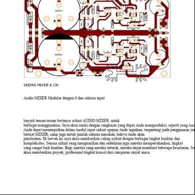
Skema Mixer 6 Ch 505p3a
November 2019 240
Ch 6 1d6y58
November 2019 37
Skema Kertas 3 Bab 6 4975u
July 2020 0
121550034 4 Ch Mixer Circuit Diagram 275541
December 2019 29
Ch 6 Test Bank.pdf 6mz5a
December 2020 0
Ch. 6 - Test Bank.pdf 2b1n6z
December 2019 34More Documents from "Verson Tito" 581kr

Penerapan Rangkaian Elektronika 256b4h
April 2020 21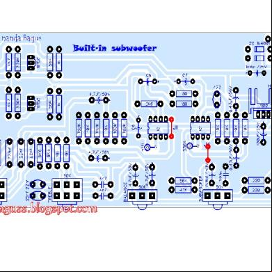
Tone Control + Subwofer Ic 4558 386x49
November 2019 166
Cara Membuat Audio Mixer Sendiri Dengan Modul Rakitan Elektronik 2 Replies Mikser Audio Adalah Perangkat Penting Yang Harus Ada Untuk Sebuah Audio System.docx 4h5c5w
October 2021 0
Skema Mixer 6 Ch 505p3a
November 2019 240
504uu
November 2020 0