11dq06 Schottky Diode 51185t
This document was ed by and they confirmed that they have the permission to share it. If you are author or own the copyright of this book, please report to us by using this report form. Report 445h4w
Overview 1s532p
& View 11dq06 Schottky Diode as PDF for free.
More details 6h715l
- Words: 927
- Pages: 5
Bulletin PD-2.288 rev. F 11/04
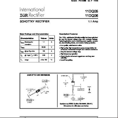
11DQ05 11DQ06 SCHOTTKY RECTIFIER
1.1 Amp
Description/ Features
Major Ratings and Characteristics Characteristics
Values
Units
IF(AV) Rectangular waveform
1.1
A
50/60
V
IFSM @ tp = 5 µs sine
150
A
VF
@ 1 Apk, TJ = 125°C
0.53
V
TJ
range
- 40 to 150
°C
VRRM
The 11DQ.. axial leaded Schottky rectifier has been optimized for very low forward voltage drop, with moderate leakage. Typical applications are in switching power supplies, converters, free-wheeling diodes, and reverse battery protection. Low profile, axial leaded outline High purity, high temperature epoxy encapsulation for enhanced mechanical strength and moisture resistance Very low forward voltage drop High frequency operation Guard ring for enhanced ruggedness and long term reliability Lead-Free plating
CASE STYLE AND DIMENSIONS
Conform to JEDEC Outline DO-204AL (DO-41) Dimensions in millimeters and inches
www.irf.com
1
11DQ05, 11DQ06 Bulletin PD-2.288 rev. F 11/04
Voltage Ratings Part number VR
Max. DC Reverse Voltage (V)
11DQ05
11DQ06
50
60
VRWM Max. Working Peak Reverse Voltage (V)
Absolute Maximum Ratings Parameters IF(AV) Max. Average Forward Current
11DQ..
Units
1.1
A
Conditions 50% duty cycle @ TC = 84°C, rectangular wave form
* See Fig. 4 IFSM
Max. Peak One Cycle Non-Repetitive
150
5µs Sine or 3µs Rect. pulse
Following any rated load condition and with 10ms Sine or 6ms Rect. pulse rated VRRM applied
A
Surge Current * See Fig. 6
25
EAS
Non-Repetitive Avalanche Energy
2.0
mJ
IAR
Repetitive Avalanche Current
1.0
A
TJ = 25 °C, IAS = 1 Amps, L = 4 mH Current decaying linearly to zero in 1 µsec Frequency limited by TJ max. VA = 1.5 x VR typical
Electrical Specifications Parameters VFM
IRM
11DQ.. Units Conditions
Max. Forward Voltage Drop * See Fig. 1 (1)
0.58 0.76 0.53
V V V
@ 1A @ 2A @ 1A
0.64
V
@ 2A
Max. Reverse Leakage Current
1.0
mA
* See Fig. 2
TJ = 25 °C
TJ = 25 °C TJ = 125 °C VR = rated VR
(1)
11
mA
TJ = 125 °C
CT
Typical Junction Capacitance
55
pF
VR = 5VDC (test signal range 100Khz to 1Mhz) 25°C
LS
Typical Series Inductance
dv/dt Max. Voltage Rate of Change
8.0
nH
10000
V/µs
Measured lead to lead 5mm from package body (Rated VR)
(1) Pulse Width < 300µs, Duty Cycle <2%
Thermal-Mechanical Specifications Parameters
11DQ.. Units Conditions
TJ
Max. Junction Temperature Range (*)
-40 to 150
Tstg
Max. Storage Temperature Range
-40 to 150
°C °C
RthJA Max. Thermal Resistance Junction to Ambient
100
°C/W DC operation Without cooling fin
RthJL Typical Thermal Resistance Junction to Lead
81
°C/W DC operation (See Fig. 4)
wt
Approximate Weight
0.33(0.012) g (oz.)
Case Style
DO-204AL(DO-41)
(*) dPtot dTj
2
<
1 Rth( j-a)
thermal runaway condition for a diode on its own heatsink
www.irf.com
11DQ05, 11DQ06 Bulletin PD-2.288 rev. F 11/04
Reverse Current - IR(mA)
100
10
T J = 150˚C
10 1
125˚C
0.1 0.01
25˚C
0.0001 0
10
20 30 40 50 60 Reverse Voltage - VR(V)
70
Fig. 2 - Typical Values of Reverse Current Vs. Reverse Voltage
T J = 150˚C T J = 125˚C
1
T J = 25˚C
100
0.1 0
0.2
0.4
0.6
0.8
1
1.2
Junction Capacitance - CT (pF)
Instantaneous Forward Current - IF (A)
0.001
T J = 25˚C
Forward Voltage Drop - VFM (V) Fig. 1 - Maximum Forward Voltage Drop Characteristics
10 0
10
20
30
40
50
60
70
Reverse Voltage - VR (V) Fig. 3 - Typical Junction Capacitance Vs. Reverse Voltage
www.irf.com
3
11DQ05, 11DQ06 Bulletin PD-2.288 rev. F 11/04
0.8
140
Average Power Loss (Watts)
Allowable Case Temperature (°C)
160
DC
120 100 80 Square wave (D = 0.50) 80% Rated Vr applied
60 40 20
D = 0.20 D = 0.25 D = 0.33 D = 0.50 D = 0.75
0.6
0.4
RMS Limit
DC
0.2 0.4 0.6 0.8
1
0.2
see note (2)
0
0 0
0.2 0.4 0.6 0.8
1
1.2 1.4 1.6
0
Average Forward Current - IF(AV) (A)
1.2 1.4 1.6
Average Forward Current - IF(AV) (A)
Fig. 4 - Maximum Ambient Temperature Vs. Average Forward Current, Printed Circuit Board Mounted
Fig. 5 - Forward Power Loss Characteristics
Non-Repetitive Surge Current-IFSM (A)
1000 At Any Rated Load Condition And With Rated Vrrm Applied Following Surge
100
10 10
100
1000
10000
Square Wave Pulse Duration - tp (microsec) Fig. 6 - Maximum Non-Repetitive Surge Current
(2) Formula used: TC = TJ - (Pd + PdREV) x RthJC ; Pd = Forward Power Loss = IF(AV) x VFM @ (IF(AV) / D) (see Fig. 6); PdREV = Inverse Power Loss = VR1 x IR (1 - D); IR @ VR1 = 80% rated VR
4
www.irf.com
11DQ05, 11DQ06 Bulletin PD-2.288 rev. F 11/04
Ordering Information Table Device Code
11
D
Q
06
TR
1
2
3
4
5
1
-
11 = 1.1A (Axial and small packages - Current is x10)
2
-
D = DO-41 package
3
-
Q = Schottky Q.. Series
4
-
10 = Voltage Ratings
5
-
TR = Tape & Reel package ( 5000 pcs) -
06 = 60V 05 = 50V
= Box package (1000 pcs)
Data and specifications subject to change without notice. This product has been designed and qualified for Industrial Level and Lead-Free. Qualification Standards can be found on IR's Web site.
IR WORLD HEADQUARTERS: 233 Kansas St., El Segundo, California 90245, USA Tel: (310) 252-7105 TAC Fax: (310) 252-7309 Visit us at www.irf.com for sales information. 11/04
www.irf.com
5
Related Documents 2w1qw
11dq06 Schottky Diode 51185t
July 2022 0
Schottky Diode 633x1d
March 2021 0
Diode e1w4a
August 2021 0
October 2022 0

Dioda Schottky Sr310-24 l4v10
December 2019 7
Datasheet (2) Fmb26l Schottky 533u4h
March 2023 0More Documents from "Mohd Najib Mohd Hussain" 2v4k4s

Ad Durrun Nafis - Syeikh Muhammad Nafis Idris Al-banjari 45691m
May 2020 32
11dq06 Schottky Diode 51185t
July 2022 0
Kitab Kejadian Insan - Jalaluddin Ar Rowi 656t1v
April 2020 35
Cbr Swing Basic.pdf f161j
July 2020 0
The Feasibility Of Calamansi Extract As An Alternative Air Freshener 426j2k
April 2020 33
December 2019 43