Types Of Automotive Relays 1i3s3p
This document was ed by and they confirmed that they have the permission to share it. If you are author or own the copyright of this book, please report to us by using this report form. Report 445h4w
Overview 1s532p
& View Types Of Automotive Relays as PDF for free.
More details 6h715l
- Words: 1,476
- Pages: 5
CHAPTER 2
ARDUINO FOR ROBOTICS
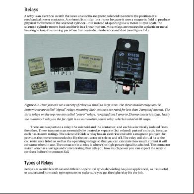
Relays A relay is an electrical switch that uses an electro-magnetic solenoid to control the position of a mechanical power or. A solenoid is similar to a motor because it uses a magnetic field to produce physical movement of the solenoid cylinder—but instead of spinning like a motor output shaft, the solenoid cylinder moves back and forth in a linear motion. Most relays are encased in a plastic or metal housing to keep the moving parts free from outside interference and dust (see Figure 2-1).
Figure 2-1. Here you can see a variety of relays in small to large sizes. The three smaller relays on the bottom row are called “signal” relays, meaning their s are rated for less than 2 amps of current. The three relays on the top row are called “power” relays, ranging from 5 amp to 25 amp ratings. Lastly, the mammoth relay on the far right is an automotive power relay, which is rated at 60 amps. There are two parts to a relay: the solenoid and the or, and each is electrically isolated from the other. These two parts can essentially be treated as separate (but related) parts of a circuit, because each has its own ratings. The solenoid inside a relay has an electrical coil with a magnetic plunger that provides the movement needed to flip the or switch on and off. The relay coil should have the coil resistance listed as well as the operating voltage so that you can calculate how much current it will consume when in use. The or in a relay is where the high-power signal is switched. The or switch also has a voltage and current rating that tells you how much power you can expect the relay to conduct before the s fail.
Types of Relays Relays are available with several different operation types depending on your application, so it is useful to understand how each type operates to make sure you get the right relay for the job.
52
CHAPTER 2
ARDUINO FOR ROBOTICS
v
Normally-Open (NO): This simply means that the two power s of the relay are connected when the relay coil is turned on and disconnected when the relay coil is turned off.
v
Normally-Closed (NC): This is the opposite of Normally-Open; the power s are connected when the relay is off and disconnected when the relay is on.
v
Latching: This means that the or switch in the relay is not spring-loaded, and it stays in whatever position it is placed into until the polarity is reversed to the coil, which returns the or switch to its original position. This is comparable to a standard home light switch—it stays on until you turn it off.
v
Non-latching: This is the “normal” type of relay that we use for failsafe switches. The relay or switch is spring-loaded and returns to the preset position unless power is applied to the coil. This is comparable to a momentary button switch—it stays on only while you press the button; otherwise, it springs back to the off position.
Relay Configurations In addition to having different operating types, relays can have their s arranged in various configurations depending on the use. There are four common types of relays that we briefly discuss— each of these relays has only solenoid coil, but a varying number of power s. Any of these relay configurations can be Normally-Open or Normally-Closed as well as latching or Non-latching as described. v
Single Pole, Single Throw (SPST): This type of relay uses one coil to control one switch with two s—there are four total s on this relay (see Figure 2-2).
Figure 2-2. This SPST relay has one pole, with one (a simple switch). v
Single Pole, Double Throw (SPDT): This type of relay uses one coil to operate one switch with three s (see Figure 2-3). The middle is for the load, the upper is for Voltage1, and the lower is for Voltage2 (or GND). This relay has five total s and is useful for switching one (Pole 1) between two different sources (Throw 1-1 and 1-2) —also called a three-way switch.
53
CHAPTER 2
ARDUINO FOR ROBOTICS
Figure 2-3. This SPDT relay has one pole, with two s (a three-way switch). v
Double Pole, Single Throw (DPST): This type of relay uses one coil to operate two independent SPST switches at the same time (see Figure 2-4). This relay has six total s and is useful for switching two loads at the same time—the two loads being switched can be associated (like a set of motor wires) or separate (like a dual-voltage power switch).
Figure 2-4. This DPST relay has two poles, and each pole has one (a double switch). v
Double Pole, Double Throw (DPDT): This type of relay uses one coil to operate two independent DPDT switches at the same time (see Figure 2-5). This relay has eight total s and can be configured as an H-bridge circuit, which is discussed in Chapter 3 (for controlling the direction of a load).
Figure 2-5. This DPDT relay has two poles, and each pole has two s (a double three-way switch).
54
CHAPTER 2
ARDUINO FOR ROBOTICS
Uses Relays have the advantage of using thick copper s, so they can easily be used to switch high currents with a relatively small amount of input current. Because the solenoid takes some time to move the or, PWM does not work with a relay. The PWM signal appears to the relay as an Analog voltage, which is either high enough to turn the relay coil on or it just stays off—but it is not generally a good idea to use a PWM signal on a relay. You can, however, use a relay to switch high-power loads using the Arduino—including AC and DC lighting, motors, heaters, appliances, and almost anything else that uses electricity. The relay is extremely useful in robotics, because it can both switch a high-power load and be controlled electronically (and thus remotely), which opens many possibilities for its use. You can use a power relay as an emergency power disconnect on a large remote-controlled robot or a remote power switch for an electric motor or lights. Using two SPDT (three-way) relay switches, we can control the direction of a DC motor. In Figure 26, you can see that if both relay coils (control 1 and control 2) are activated, the upper motor terminal will be connected to the positive voltage supply and the lower terminal will be connected to the negative voltage supply, causing the motor to spin in a clockwise direction. If power is removed from both relay coils, the upper motor terminal will be connected to the negative voltage supply and the lower terminal to the positive voltage supply, causing the motor to spin in a counter-clockwise direction.
Figure 2-6. These figures show how a DC motor can be controlled using two SPDT relay switches (or one DPDT relay switch). Before we can use the relay, we need to calculate how much power is needed to drive the relay coil. If the relay coil draws more current than 40mA that the Arduino can supply, an interface switch will be needed to turn on the relay coil using the Arduino.
Calculating Current Draw To determine the amount of current that a relay draws, you must first determine the coil resistance by checking the relay datasheet. If this information is not available, you can measure the resistance with a
55
CHAPTER 2
ARDUINO FOR ROBOTICS
multi-meter. Using the coil resistance and voltage rating of the relay, use Ohm’s law to calculate the current draw from the coil. In Figure 2-7, you can see a sample of the datasheet from the Omron G5-CA series relays. As you can see, the relay is available with three different coil voltages (5v, 12v, or 24v). The coil resistance for each model is listed below along with the rated current. The 5v version of this relay coil has a rated current of 40mA, which is low enough to be powered by the Arduino without using an interface circuit.
Figure 2-7. This is a sample portion of a relay datasheet; you can see both the coil and ratings. Even though this particular datasheet displays the rated current of the relay coil, some relays have only the operating voltage listed. In this case, you must manually measure the resistance of the relay coil using your multi-meter and then use Ohm’s law to calculate the current draw. From the datasheet in Figure 2-7, we use Ohm’s law to the current draw for a 5v relay with a coil resistance of 125 ohms. V=I*R I=V/R I = 5v / 125 ohms I = 0.040 amps (40mA) —The datasheet is correct!
56
ARDUINO FOR ROBOTICS
Relays A relay is an electrical switch that uses an electro-magnetic solenoid to control the position of a mechanical power or. A solenoid is similar to a motor because it uses a magnetic field to produce physical movement of the solenoid cylinder—but instead of spinning like a motor output shaft, the solenoid cylinder moves back and forth in a linear motion. Most relays are encased in a plastic or metal housing to keep the moving parts free from outside interference and dust (see Figure 2-1).
Figure 2-1. Here you can see a variety of relays in small to large sizes. The three smaller relays on the bottom row are called “signal” relays, meaning their s are rated for less than 2 amps of current. The three relays on the top row are called “power” relays, ranging from 5 amp to 25 amp ratings. Lastly, the mammoth relay on the far right is an automotive power relay, which is rated at 60 amps. There are two parts to a relay: the solenoid and the or, and each is electrically isolated from the other. These two parts can essentially be treated as separate (but related) parts of a circuit, because each has its own ratings. The solenoid inside a relay has an electrical coil with a magnetic plunger that provides the movement needed to flip the or switch on and off. The relay coil should have the coil resistance listed as well as the operating voltage so that you can calculate how much current it will consume when in use. The or in a relay is where the high-power signal is switched. The or switch also has a voltage and current rating that tells you how much power you can expect the relay to conduct before the s fail.
Types of Relays Relays are available with several different operation types depending on your application, so it is useful to understand how each type operates to make sure you get the right relay for the job.
52
CHAPTER 2
ARDUINO FOR ROBOTICS
v
Normally-Open (NO): This simply means that the two power s of the relay are connected when the relay coil is turned on and disconnected when the relay coil is turned off.
v
Normally-Closed (NC): This is the opposite of Normally-Open; the power s are connected when the relay is off and disconnected when the relay is on.
v
Latching: This means that the or switch in the relay is not spring-loaded, and it stays in whatever position it is placed into until the polarity is reversed to the coil, which returns the or switch to its original position. This is comparable to a standard home light switch—it stays on until you turn it off.
v
Non-latching: This is the “normal” type of relay that we use for failsafe switches. The relay or switch is spring-loaded and returns to the preset position unless power is applied to the coil. This is comparable to a momentary button switch—it stays on only while you press the button; otherwise, it springs back to the off position.
Relay Configurations In addition to having different operating types, relays can have their s arranged in various configurations depending on the use. There are four common types of relays that we briefly discuss— each of these relays has only solenoid coil, but a varying number of power s. Any of these relay configurations can be Normally-Open or Normally-Closed as well as latching or Non-latching as described. v
Single Pole, Single Throw (SPST): This type of relay uses one coil to control one switch with two s—there are four total s on this relay (see Figure 2-2).
Figure 2-2. This SPST relay has one pole, with one (a simple switch). v
Single Pole, Double Throw (SPDT): This type of relay uses one coil to operate one switch with three s (see Figure 2-3). The middle is for the load, the upper is for Voltage1, and the lower is for Voltage2 (or GND). This relay has five total s and is useful for switching one (Pole 1) between two different sources (Throw 1-1 and 1-2) —also called a three-way switch.
53
CHAPTER 2
ARDUINO FOR ROBOTICS
Figure 2-3. This SPDT relay has one pole, with two s (a three-way switch). v
Double Pole, Single Throw (DPST): This type of relay uses one coil to operate two independent SPST switches at the same time (see Figure 2-4). This relay has six total s and is useful for switching two loads at the same time—the two loads being switched can be associated (like a set of motor wires) or separate (like a dual-voltage power switch).
Figure 2-4. This DPST relay has two poles, and each pole has one (a double switch). v
Double Pole, Double Throw (DPDT): This type of relay uses one coil to operate two independent DPDT switches at the same time (see Figure 2-5). This relay has eight total s and can be configured as an H-bridge circuit, which is discussed in Chapter 3 (for controlling the direction of a load).
Figure 2-5. This DPDT relay has two poles, and each pole has two s (a double three-way switch).
54
CHAPTER 2
ARDUINO FOR ROBOTICS
Uses Relays have the advantage of using thick copper s, so they can easily be used to switch high currents with a relatively small amount of input current. Because the solenoid takes some time to move the or, PWM does not work with a relay. The PWM signal appears to the relay as an Analog voltage, which is either high enough to turn the relay coil on or it just stays off—but it is not generally a good idea to use a PWM signal on a relay. You can, however, use a relay to switch high-power loads using the Arduino—including AC and DC lighting, motors, heaters, appliances, and almost anything else that uses electricity. The relay is extremely useful in robotics, because it can both switch a high-power load and be controlled electronically (and thus remotely), which opens many possibilities for its use. You can use a power relay as an emergency power disconnect on a large remote-controlled robot or a remote power switch for an electric motor or lights. Using two SPDT (three-way) relay switches, we can control the direction of a DC motor. In Figure 26, you can see that if both relay coils (control 1 and control 2) are activated, the upper motor terminal will be connected to the positive voltage supply and the lower terminal will be connected to the negative voltage supply, causing the motor to spin in a clockwise direction. If power is removed from both relay coils, the upper motor terminal will be connected to the negative voltage supply and the lower terminal to the positive voltage supply, causing the motor to spin in a counter-clockwise direction.
Figure 2-6. These figures show how a DC motor can be controlled using two SPDT relay switches (or one DPDT relay switch). Before we can use the relay, we need to calculate how much power is needed to drive the relay coil. If the relay coil draws more current than 40mA that the Arduino can supply, an interface switch will be needed to turn on the relay coil using the Arduino.
Calculating Current Draw To determine the amount of current that a relay draws, you must first determine the coil resistance by checking the relay datasheet. If this information is not available, you can measure the resistance with a
55
CHAPTER 2
ARDUINO FOR ROBOTICS
multi-meter. Using the coil resistance and voltage rating of the relay, use Ohm’s law to calculate the current draw from the coil. In Figure 2-7, you can see a sample of the datasheet from the Omron G5-CA series relays. As you can see, the relay is available with three different coil voltages (5v, 12v, or 24v). The coil resistance for each model is listed below along with the rated current. The 5v version of this relay coil has a rated current of 40mA, which is low enough to be powered by the Arduino without using an interface circuit.
Figure 2-7. This is a sample portion of a relay datasheet; you can see both the coil and ratings. Even though this particular datasheet displays the rated current of the relay coil, some relays have only the operating voltage listed. In this case, you must manually measure the resistance of the relay coil using your multi-meter and then use Ohm’s law to calculate the current draw. From the datasheet in Figure 2-7, we use Ohm’s law to the current draw for a 5v relay with a coil resistance of 125 ohms. V=I*R I=V/R I = 5v / 125 ohms I = 0.040 amps (40mA) —The datasheet is correct!
56
Related Documents 2w1qw
Types Of Automotive Relays 1i3s3p
December 2019 49
Basics Of Relays And Different Types Of Relays - All Instrumentation 2x5431
November 2019 41
Relays 5y15
August 2021 0
Relays 5y15
November 2022 0
Automotive 594cn
November 2019 123
Ee Relays 3x1n24
December 2019 69More Documents from "Gopi Krishna" 4ruc

Book List From Toppers 3276t
December 2019 46
Latest Zerodha Margin List 1b5i4n
August 2021 0
Payment Of Gratuity Central Rules 1972 s6n50
January 2022 0
It s In Uae 214v4p
November 2020 0
Ece Resume Format For Freshers Resume i4t2c
November 2019 147