Liquid Level Control System 2b4v2z
This document was ed by and they confirmed that they have the permission to share it. If you are author or own the copyright of this book, please report to us by using this report form. Report 445h4w
Overview 1s532p
& View Liquid Level Control System as PDF for free.
More details 6h715l
- Words: 902
- Pages: 3
EXP. #6 Liquid level control system
1
Objective 1) To construct and study a liquid level control system. 2) To study the effect of the PID controller on the closed loop system. 3) To study the effect of disturbance on the system performance.
Equipments • • • •
Process control simulator. Scope. Volt-meter. Liquid level control system.
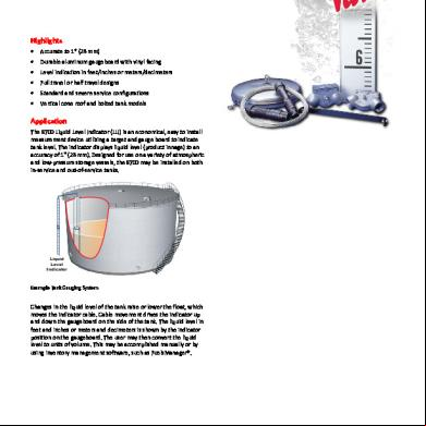
Theory In this experiment, the examiner will test a system to control a fluid level in a container. This system keep the fluid on the certain level or desired level and control two type of valve the. first the inlets valve which allow the fluid to enter the container if its level go down, the second type if goes the opposite the first that if the fluid goes up the desired level the system open the valve to allow the fluid to exit.
Procedure 1) Adjust the following values: Process control simulator Liquid level control system Scope Set value @ 6V “the input” Pump output @ 1 500mV/cm “vertical” All τ switches @ slow =1sec Valve @ middle 20sec/cm “horizontal” P%=50% “P=0.5” P-controller 2) Adjust the knob in Liquid level control system to make the water level @ 50mm, display the error signal. 3) Switch the output valve to one then notice the time response and plot it. 4) Return the valve to middle then notice the time response and plot it. PI-controller 5) Add I with τ=7.5sec then repeat steps 2, 3 and 4. PID controller 6) Add D with τ=1sec then repeat steps 2, 3 and 4. 7) Repeat 6 with τ=0.6sec then repeat steps 2, 3 and 4.
Result ’for the calculation see the calculation Part’ There are no numerical results. The output shape in one the sketch paper in the Pre-LAB.
2
EXP. #6 Liquid level control system
Answering of the Questions Q1) X
a a +b
+
Σ
G ( s ) AK v + Ps K P K( 1 +R fC f s )
R 1 + ARs
Y
-
b a +b ⎡ ⎤ ⎢ ⎥ RG ( s ) AK + RP K K + P K RR C s s s Y(s) ⎢ P P a f f ⎥ .( = X ( s ) ⎢K ( 1 + R C s )( 1 + ARs ) + ( RG( s ) AK + RP K K + P K RR C s )( b ) ⎥ a + b s P s P ⎢ f f f f a + b ⎥⎦ ⎣ ⎡ ⎤ RG ( s ) AK + RP K K + P K RR C s ⎢ ⎥ s s Y(s) P P f f =⎢ ⎥. X ( s ) ⎢K ( 1 + R C s )( 1 + ARs )( a ) + ( RG( s ) AK + RPsK K + PsK RR C s ) ⎥ P P f f f f a +b ⎢⎣ ⎥⎦ ⎡ ⎤ ⎢ ⎥ ⎢ ⎥ RG( s ) AK + RPsK P K + PsK P RR f C f s Y(s) ⎢ ⎥. = ⎢ ( R C + AR ) + P K RR C ⎥ ( 1 + RPsK P K ) RAKG( s ) X ( s ) ⎢s 2 + f f s P f f s+ + aK ⎥⎥ ARR f C f ARR f C f ⎢ ( ARR f C f )( ) ⎢⎣ a + b ⎥⎦
Where G(s) is the transfer function of the PID controller . The system types depend on G(s) Type of PID
order
Transfer Function ( R f C f + AR ) + Ps K P RR f C f
ζ=
ARR f C f aK + RPs K P K ) RAKU a + b + 2 aK aK ( ARR f C f )( ) ( ARR f C f )( ) a +b a +b aK ( + RPs K P K ) RAKU a b + = + aK aK ( ARR f C f )( ) ( ARR f C f )( ) a +b a +b (
PSecond controller order
U
w PIcontroller
Third order
U+
s TI
n
Can’t calculated by this equation
)
3
EXP. #6 Liquid level control system
( R f C f + AR ) + Ps K P RR f C f + RAK
ζ=
ARR f C f aK + RPs K P K ) RAKU + a b 2 + aK aK ( ARR f C f )( ) ( ARR f C f )( ) a +b a +b (
PDSecond controller order
U + TDs
w PIDThird U + ( T + 1 ) s D Ts controller order Where U, TD and TI are constant.
n
=
( aK + RPsK P K ) RAKU a +b + ( ARR f C f )( aK ) ( ARR f C f )( aK ) a +b a +b
Can’t calculated by this equation
Conclusion the Transfer function of the system show that the system has a good response when the controller is only P. Adding another controller with P will change the response, the adding of I increase the over shot of the system. In the mean while, the adding of the D oscaltion in the steady state but it can be reduced by reduce the τ.
1
Objective 1) To construct and study a liquid level control system. 2) To study the effect of the PID controller on the closed loop system. 3) To study the effect of disturbance on the system performance.
Equipments • • • •
Process control simulator. Scope. Volt-meter. Liquid level control system.
Theory In this experiment, the examiner will test a system to control a fluid level in a container. This system keep the fluid on the certain level or desired level and control two type of valve the. first the inlets valve which allow the fluid to enter the container if its level go down, the second type if goes the opposite the first that if the fluid goes up the desired level the system open the valve to allow the fluid to exit.
Procedure 1) Adjust the following values: Process control simulator Liquid level control system Scope Set value @ 6V “the input” Pump output @ 1 500mV/cm “vertical” All τ switches @ slow =1sec Valve @ middle 20sec/cm “horizontal” P%=50% “P=0.5” P-controller 2) Adjust the knob in Liquid level control system to make the water level @ 50mm, display the error signal. 3) Switch the output valve to one then notice the time response and plot it. 4) Return the valve to middle then notice the time response and plot it. PI-controller 5) Add I with τ=7.5sec then repeat steps 2, 3 and 4. PID controller 6) Add D with τ=1sec then repeat steps 2, 3 and 4. 7) Repeat 6 with τ=0.6sec then repeat steps 2, 3 and 4.
Result ’for the calculation see the calculation Part’ There are no numerical results. The output shape in one the sketch paper in the Pre-LAB.
2
EXP. #6 Liquid level control system
Answering of the Questions Q1) X
a a +b
+
Σ
G ( s ) AK v + Ps K P K( 1 +R fC f s )
R 1 + ARs
Y
-
b a +b ⎡ ⎤ ⎢ ⎥ RG ( s ) AK + RP K K + P K RR C s s s Y(s) ⎢ P P a f f ⎥ .( = X ( s ) ⎢K ( 1 + R C s )( 1 + ARs ) + ( RG( s ) AK + RP K K + P K RR C s )( b ) ⎥ a + b s P s P ⎢ f f f f a + b ⎥⎦ ⎣ ⎡ ⎤ RG ( s ) AK + RP K K + P K RR C s ⎢ ⎥ s s Y(s) P P f f =⎢ ⎥. X ( s ) ⎢K ( 1 + R C s )( 1 + ARs )( a ) + ( RG( s ) AK + RPsK K + PsK RR C s ) ⎥ P P f f f f a +b ⎢⎣ ⎥⎦ ⎡ ⎤ ⎢ ⎥ ⎢ ⎥ RG( s ) AK + RPsK P K + PsK P RR f C f s Y(s) ⎢ ⎥. = ⎢ ( R C + AR ) + P K RR C ⎥ ( 1 + RPsK P K ) RAKG( s ) X ( s ) ⎢s 2 + f f s P f f s+ + aK ⎥⎥ ARR f C f ARR f C f ⎢ ( ARR f C f )( ) ⎢⎣ a + b ⎥⎦
Where G(s) is the transfer function of the PID controller . The system types depend on G(s) Type of PID
order
Transfer Function ( R f C f + AR ) + Ps K P RR f C f
ζ=
ARR f C f aK + RPs K P K ) RAKU a + b + 2 aK aK ( ARR f C f )( ) ( ARR f C f )( ) a +b a +b aK ( + RPs K P K ) RAKU a b + = + aK aK ( ARR f C f )( ) ( ARR f C f )( ) a +b a +b (
PSecond controller order
U
w PIcontroller
Third order
U+
s TI
n
Can’t calculated by this equation
)
3
EXP. #6 Liquid level control system
( R f C f + AR ) + Ps K P RR f C f + RAK
ζ=
ARR f C f aK + RPs K P K ) RAKU + a b 2 + aK aK ( ARR f C f )( ) ( ARR f C f )( ) a +b a +b (
PDSecond controller order
U + TDs
w PIDThird U + ( T + 1 ) s D Ts controller order Where U, TD and TI are constant.
n
=
( aK + RPsK P K ) RAKU a +b + ( ARR f C f )( aK ) ( ARR f C f )( aK ) a +b a +b
Can’t calculated by this equation
Conclusion the Transfer function of the system show that the system has a good response when the controller is only P. Adding another controller with P will change the response, the adding of I increase the over shot of the system. In the mean while, the adding of the D oscaltion in the steady state but it can be reduced by reduce the τ.
Related Documents 2w1qw

Liquid Level Control System 2b4v2z
December 2019 50
Water Level Control System 305p1
December 2019 45
Water Level Control System 305p1
December 2019 41
Air Suspension Level Control System 465117
November 2019 52
Ll-3 Liquid Level Switch 4o1c2u
July 2022 0